Skip to content

AI · Data centers · Edge · Industrial

More compute.
Smarter cooling.

Rack-based immersion cooling for AI, data centers, edge computing, and demanding industrial environments.

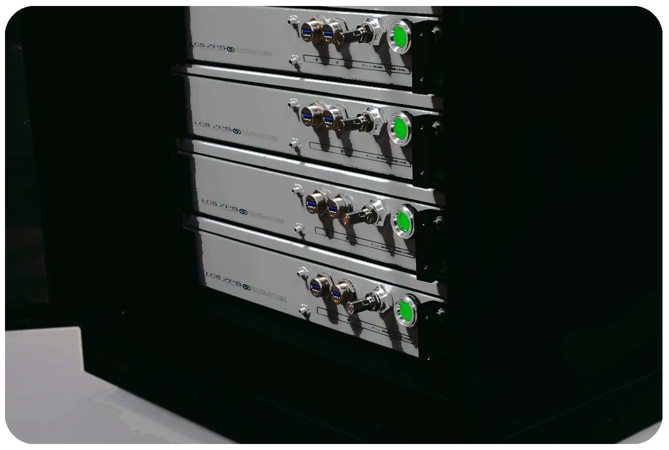
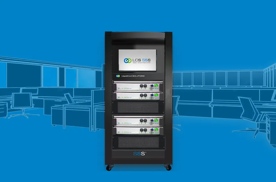
Close-up of LCS ZPServer immersion-cooled chassis installed in a standard rack, with fluid quick-connects on the front

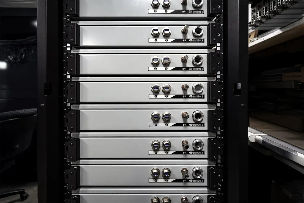
LCS ZPServers in a 19″ rack · flow lines illustrative

Immersion R&D since
2006
Immersion R&D since
Standard EIA / OCP racks
19″
Standard EIA / OCP racks
Server fans
0
Server fans
Deployment paths
3
Deployment paths

What is TIDF?

Total Liquid Immersion with Directed Flow™ sends the coolest dielectric fluid straight to the hottest chips, then immerses every other component in a sealed chassis, removing heat with liquid instead of air, in a standard rack.

Solutions

The challenge

Denser computing turns heat into an infrastructure problem.

Every generation of CPUs and GPUs packs more power into each server. Air can only carry so much heat, so dense AI and HPC racks push facilities toward bigger air handlers, chillers, and more floor space, or toward throttled hardware.

The consequences land on the people who run the infrastructure:

  • Deployment flexibilityWhere can high-density compute physically go?
  • Operating costHow much power goes to cooling instead of computing?
  • ReliabilityHow exposed are electronics to heat, dust, and humidity?
  • SpaceHow many racks, or rooms, does the workload need?

How the technology works

Three stages, one sealed chassis.

  1. 1

    Cool fluid reaches high-heat components

    Single-phase dielectric fluid is piped first through engineered heatsinks on CPUs and GPUs.

  2. 2

    Immersion collects remaining heat

    Leaving the heatsinks, fluid floods the chassis and absorbs heat from memory, storage, and power electronics.

  3. 3

    Heated fluid exits for heat exchange

    Warm fluid leaves the chassis to a heat exchanger, where heat is rejected or captured for reuse, and returns cooled.

Technology deep-dive
How Total Liquid Immersion with Directed Flow worksA sealed chassis. Stage 1: cool dielectric fluid enters and is piped directly to heatsinks on the hottest chips. Stage 2: fluid leaves the heatsinks and immerses the remaining electronics. Stage 3: heated fluid exits the chassis to a heat exchanger and returns cooled.SEALED, LIQUID-TIGHT CHASSISCPU/GPUCPU/GPU123Cool fluid inHeated fluid outto heat exchange1 Directed to hottest chips2 Immerses remaining electronics3 Exits, cooled, returns
Illustrative schematic, not to scale and not a drawing of a specific product.

Our view

Air cooling was built for a different era of computing. We cool the next one with liquid, in the racks you already run.

Why rack-based immersion

Liquid cooling that fits the infrastructure you already run.

Immersion tanks lay servers horizontally in a bath. LCS seals each server in its own chassis and keeps the vertical 19″ rack.

Compare cooling approaches
Compatibility
Chassis insert into standard EIA and OCP racks, and are configured around your choice of CPUs and GPUs.
Incremental deployment
Add servers one at a time, alongside existing air-cooled equipment, rather than committing to a tank room.
Service access
Pull a server from the rack to maintain it; no lifting components out of a fluid bath.
Fluid requirements
Each chassis holds its own fluid (approx. 5 gal per 2U ZPServer). LCS states this is about one-third of the fluid of tank systems.
Space
LCS's published comparison: 9.5 sq ft per rack vs. 22 sq ft per tank at the same compute density. Baseline details pending confirmation.
Facility water
Where liquid-to-liquid exchange is used, connections come from above, like cold-plate infrastructure.

Evidence & results

Tested in the lab and in an operating data center.

Field test · Grid Catalyst 2025

GPU performance per watt vs. air cooling

Through the Grid Catalyst 2025 Demonstration Cohort, LCS tested TIDF-cooled GPU servers with partner Vaultas. LCS reports up to 20% higher GPU performance per watt than air cooling in that test. Full methodology is in the report, available on request.

LCS chart comparing GFLOPS per watt for one to four GPUs under air cooling and TIDF liquid coolingWhat was tested

Technical evaluation · NREL

National Renewable Energy Laboratory evaluation

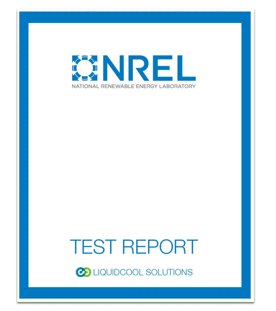
LCS reports that the NREL technical evaluation showed cooling PUEs of 1.03 and heat-recovery efficiencies of 90–95%, and that NREL described the approach as a “gold standard” for building-connected data centers. The evaluation is available on request.

Cover of the NREL technical evaluation of LiquidCool Solutions technologyRead the summary
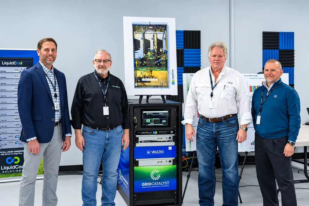
LCS engineering and operations leaders with the Grid Catalyst immersion-cooled server rack

Engineering credibility

Working on immersion cooling since 2006.

LCS began with immersion-cooled high-performance gaming systems in 2006 and turned to servers six years later. Today its engineers and technicians, whose careers include Dell, IBM, HP, Cray, Silicon Graphics, and Western Digital, design and build systems in Rochester, Minnesota, backed by a portfolio of patents in chassis-based single-phase immersion.

Meet the team

Next step

Let’s solve your cooling challenge.

Tell us about your workload, site, and timeline. An LCS engineer will help you assess whether rack-based immersion fits your infrastructure.